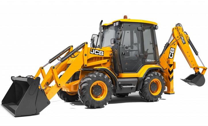
The steering column of the JCB Backhoe Loader 3CX can be tilted to improve the reach and comfort of the operator. This type of assembly is known as a ’tilt column’. The illustration on the adjacent page is a guide to the removal and replacement process.This guide provides step-by-step instructions for removing and replacing the steering column of the JCB Backhoe Loader 3CX. Following these instructions carefully will ensure a successful removal and replacement process.
Related Content:
2023 JCB ServiceMaster 4 Free Download
Removal:
1. Park the machine on level ground, engage the parking brake, and set the transmission to neutral. Lower the loader arms to the ground. Switch off the engine, remove the starter key, and disconnect the battery.
2. Remove the steering wheel as shown in diagram A.
3. Remove socket screws B and take off the steering column pedestal cover.
4. Remove the control column switches C.
5. Remove socket screw D, which secures the gas damper strut E.
6. Remove socket screws F and lift up the rubber protective cover behind the brake pedals to access the flexible coupling.
7. Remove the coupling bolt G and shoulder bolts H. Carefully withdraw the steering column assembly (with the gas damper strut attached) from the flexible coupling J.
Replacement:
The replacement process is the reverse of the removal sequence.
1. Apply JCB Threadlocker and Sealer to the threads of nuts T.
2. Note that the coupling bolt G must engage with the cut-out in the shaft.
3. After re-fitting, check that the steering tilt functions correctly and that the direction indicators and lights operate properly.
4. Ensure that the wires from the brake pedal switch do not rub against the steering column.
Torque Settings:
– Socket Screw D: 14 Nm / 1.4 kgf m / 10.3 lbf ft
– Shoulder Bolts H: 40 Nm / 4.1 kgf m / 29.5 lbf ft
Dismantling and Assembly:
The illustration on the adjacent page is a guide to dismantling and assembly.
Dismantling:
1. Using a screwdriver in the slot, carefully pry out the dust seal L from the outer column tube.
2. Remove the external circlip M, washer N, and tolerance ring P. Withdraw the steering shaft from the outer column tube and pivot bracket.
Note: The top and bottom bearings R and S housed in the outer column tube cannot be serviced. They may be removed for cleaning and inspection, but if the bearing(s) have failed, a new outer column tube and pivot bracket assembly must be used.
Note: The gas damper strut E is also a non-serviceable part. If the damper is faulty, it must be replaced with a new one.
Assembly:
The assembly process is the reverse of the dismantling sequence.

Leave a Reply